Daniel Micanek virtual Blog – Like normal Dan, but virtual.
Category: ESXi
The “ESXi” blog category focuses on VMware ESXi, a bare-metal hypervisor provided by VMware. This specific category offers an in-depth look at ESXi, with an emphasis on ESXCLI commands, ESXCLI Mindmap, and VMware Tools version mapping with Release Notes. The content includes detailed guides and tutorials for using ESXCLI commands, essential for efficient management and troubleshooting in ESXi environments. It also features illustrative ESXCLI Mindmaps, helping users better understand and navigate the complex structure of ESXCLI. The section on mapping VMware Tools versions with Release Notes provides useful information about different versions of VMware Tools and their specific features and enhancements.
As the IT industry continues to evolve, so do the platforms and hardware that support our digital infrastructure. One significant upcoming change is related to Intel’s Skylake generation of processors, which has entered the End of Servicing Update (ESU) and End of Servicing Lifetime (EOSL) phase. By December 31, 2023, Intel will officially stop providing updates for Skylake server-class processors, including the Xeon Scalable Processors (SP) series. This change is set to impact future VMware vSphere releases, as VMware plans to discontinue support for Intel Skylake CPUs in its next major release following vSphere 8.x.
Why Skylake CPUs are Being Phased Out
Intel’s Skylake architecture, introduced in 2015, has been widely adopted in server environments for its balance of performance and power efficiency. The Xeon Scalable Processor series, which is part of the Skylake generation, has been foundational in many data centers around the world. However, as technology progresses, older generations of processors become less relevant in the context of modern workloads and new advancements in CPU architectures.
Impact on VMware vSphere Users
With VMware announcing plans to drop support for Skylake CPUs in a future major release after vSphere 8.x, organizations relying on these processors need to start planning for hardware refreshes. As VMware’s virtualization platform evolves, it is optimized for more modern CPU architectures that offer enhanced performance, security, and energy efficiency.
Starting with vSphere 8.0 Update 3, nConnect support has been added for NFS v4.1 datastores. This feature enables multiple connections using a single IP address within a session, thereby extending session trunking functionality to that IP. With nConnect, multipathing and nConnect coexist, allowing for more flexible and efficient network configurations.
Benefits of nConnect
Traditionally, vSphere NFSv4.1 implementations create a single TCP/IP connection from each host to each datastore. This setup can become a bottleneck in scenarios requiring high performance. By enabling multiple connections per IP, nConnect significantly enhances data throughput and performance. Here’s a quick overview of the benefits:
Increased Performance: Multiple connections can be established per session, reducing congestion and improving data transfer speeds.
Flexibility: Customers can configure datastores with multiple IPs to the same server and also multiple connections with the same IP.
Scalability: Supports up to 8 connections per IP, enhancing scalability for demanding workloads.
Configuring nConnect
Adding a New NFSv4.1 Datastore
When adding a new NFSv4.1 datastore, you can specify the number of connections at the time of the mount using the following command:
By default, the maximum number of connections per session is set to 4. However, this can be increased to 8 using advanced NFS options. Here’s how you can configure it:
Set the maximum number of connections to 8:esxcfg-advcfg -s 8 /NFS41/MaxNConnectConns
Verify the configuration:esxcfg-advcfg -g /NFS41/MaxNConnectConns
The total number of connections used across all mounted NFSv4.1 datastores is limited to 256.
Modifying Connections for an Existing NFSv4.1 Datastore
For an existing NFSv4.1 datastore, the number of connections can be increased or decreased at runtime using the following command:
esxcli storage nfs41 param set -v <volume-label> -c <number_of_connections>
Multipathing and nConnect Coexistence
There is no impact on multipathing when using nConnect. Both NFSv4.1 nConnect and multipaths can coexist seamlessly. Connections are created for each of the multipathing IPs, allowing for enhanced redundancy and performance.
Example Configuration with Multiple IPs
To add a datastore with multiple IPs and specify the number of connections, use:
This command ensures that multiple connections are created for each of the specified IPs, leveraging the full potential of nConnect.
Summary
The introduction of nConnect support in vSphere 8.0 U3 for NFS v4.1 datastores marks a significant enhancement in network performance and flexibility. By allowing multiple connections per IP, nConnect addresses the limitations of single connection setups, providing a robust solution for high-performance environments. Whether you’re configuring a new datastore or updating an existing one, nConnect offers a scalable and efficient way to manage your NFS workloads.
In the complex world of virtualization, developers often face the challenge of debugging guest operating systems and applications. A practical solution lies in converting virtual machine snapshots to memory dumps. This blog post delves into how you can efficiently use the vmss2core tool to transform a VM checkpoint, be it a snapshot or suspend file, into a core dump file, compatible with standard debuggers.
Step-by-Step Guide
Break down the process into clear, step-by-step instructions. Use bullet points or numbered lists for easier readability. Example:
Step 1: Create and download a virtual machine Snapshots .vmsn and .vmem
Select the Problematic Virtual Machine
In your VMware environment, identify and select the virtual machine experiencing issues.
Replicate the Issue
Attempt to replicate the problem within the virtual machine to ensure the snapshot captures the relevant state.
Take a Snapshot
Right-click on the virtual machine.
Navigate to Snapshots → Take snapshot
Enter a name for the snapshot.
Ensure “Snapshot the Virtual Machine’s memory” is checked
Click ‘CREATE’ to proceed.
Access VM Settings
Right-click on the virtual machine again.
Select ‘Edit Settings’
Navigate to Datastores
Choose the virtual machine and click on ‘Datastores’.
Click on the datastore name
Download the Snapshot
Locate the .vmsn ans .vmem files (VMware Snapshot file).
Select the file, click ‘Download’, and save it locally.
Step 2: Locate Your vmss2core Installation
For Windows (32bit): Navigate to C:\Program Files\VMware\VMware Workstation\
For Windows (64bit): Go to C:\Program Files(x86)\VMware\VMware Workstation\
For Linux: Access /usr/bin/
For Mac OS: Find it in /Library/Application Support/VMware Fusion/
Note: If vmss2core isn’t in these directories, download it from New Flings Link (use at your own risk).
For general use: vmss2core.exe -W [VM_name].vmsn [VM_name].vmem
For Windows 8/8.1, Server 2012, 2016, 2019: vmss2core.exe -W8 [VM_name].vmsn [VM_name].vmem
For Linux: ./vmss2core-Linux64 -N [VM_name].vmsn[VM_name].vmemNote: Replace [VM_name] with your virtual machine’s name. The flag -W, -W8, or -N corresponds to the guest OS.
#vmss2core.exe
vmss2core version 20800274 Copyright (C) 1998-2022 VMware, Inc. All rights reserved. A tool to convert VMware checkpoint state files into formats that third party debugger tools understand. It can handle both suspend (.vmss) and snapshot (.vmsn) checkpoint state files (hereafter referred to as a 'vmss file') as well as both monolithic and non-monolithic (separate .vmem file) encapsulation of checkpoint state data. Usage: GENERAL: vmss2core [[options] | [-l linuxoffsets options]] \ <vmss file> [<vmem file>] The "-l" option specifies offsets (a stringset) within the Linux kernel data structures, which is used by -P and -N modes. It is ignored with other modes. Please use "getlinuxoffsets" to automatically generate the correct stringset value for your kernel, see README.txt for additional information. Without options one vmss.core<N> per vCPU with linear view of memory is generated. Other types of core files and output can be produced with these options: -q Quiet(er) operation. -M Create core file with physical memory view (vmss.core). -l str Offset stringset expressed as 0xHEXNUM,0xHEXNUM,... . -N Red Hat crash core file for arbitrary Linux version described by the "-l" option (vmss.core). -N4 Red Hat crash core file for Linux 2.4 (vmss.core). -N6 Red Hat crash core file for Linux 2.6 (vmss.core). -O <x> Use <x> as the offset of the entrypoint. -U <i> Create linear core file for vCPU <i> only. -P Print list of processes in Linux VM. -P<pid> Create core file for Linux process <pid> (core.<pid>). -S Create core for 64-bit Solaris (vmcore.0, unix.0). Optionally specify the version: -S112 -S64SYM112 for 11.2. -S32 Create core for 32-bit Solaris (vmcore.0, unix.0). -S64SYM Create text symbols for 64-bit Solaris (solaris.text). -S32SYM Create text symbols for 32-bit Solaris (solaris.text). -W Create WinDbg file (memory.dmp) with commonly used build numbers ("2195" for Win32, "6000" for Win64). -W<num> Create WinDbg file (memory.dmp), with <num> as the build number (for example: "-W2600"). -WK Create a Windows kernel memory only dump file (memory.dmp). -WDDB<num> or -W8DDB<num> Create WinDbg file (memory.dmp), with <num> as the debugger data block address in hex (for example: "-W12ac34de"). -WSCAN Scan all of memory for Windows debugger data blocks (instead of just low 256 MB). -W8 Generate a memory dump file from a suspended Windows 8 VM. -X32 <mach_kernel> Create core for 32-bit Mac OS. -X64 <mach_kernel> Create core for 64-bit Mac OS. -F Create core for an EFI firmware exception. -F<adr> Create core for an EFI firmware exception with system context at the given guest virtual address.
Rebuilding a VMX file from vmware.log in VMware ESXi can be crucial for restoring a virtual machine’s configuration. This guide will walk you through the process using SSH according KB 1023880, but with update for ESXi 8.0. It was necessary add #!/bin/ash because of error “Operation not permitted”.
Step 1: SSH into Your ESXi Host
First, ensure SSH is enabled on your ESXi host. Then, use an SSH client to connect to the host.
Step 2: Navigate to the Virtual Machine’s Directory
Change to the directory where your VM resides. This is usually under /vmfs/volumes/.
cd /vmfs/volumes/name-volume/name-vm
Step 3: Create and Prepare the Script File
Create a new file named vmxrebuild.sh and make it executable:
touch vmxrebuild.sh && chmod +x vmxrebuild.sh
Step 4: Edit the Script File for ESXi 8
Edit the vmxrebuild.sh file using the vi editor:
Run vi vmxrebuild.sh.
Press i to enter insert mode.
Copy and paste the following script (adjust for your ESXi host version).
This process extracts the necessary configuration details from the vmware.log file and recreates the VMX file, which is vital for VM configuration. Always back up your VM files before performing such operations.
The Raspberry Pi 5, a remarkable addition to the Raspberry Pi series, boasts an advanced configuration with five active PCI Express lanes. These lanes are ingeniously distributed with four dedicated to the innovative RP1 chip, which supports a variety of I/O functionalities such as USB, Ethernet, MIPI Camera and Display, and GPIO. Additionally, there’s a fifth lane that interfaces with a novel external PCIe connector.
In its default setup, the Raspberry Pi 5 operates all PCIe lanes at Gen 2.0 speeds, offering a throughput of approximately 5 GT/sec per lane. This standard setting is fixed for the internal lanes connected to the RP1 chip. However, for users seeking enhanced performance, there’s an exciting tweak available for the external PCIe connector. By simply adding a couple of lines to the /boot/config.txt file and rebooting your device, you can elevate the external connector to Gen 3.0 speeds. This upgrade boosts the data transfer rate to 8 GT/sec, nearly doubling the default speed.
To achieve this, insert the following commands in your /boot/config.txt file:
dtparam=pciex1
dtparam=pciex1_gen=3
After these adjustments and a system reboot, your Raspberry Pi 5 will operate the external PCIe lane at the faster Gen 3.0 speed, unlocking new potential for your projects and applications.
With the release of ONTAP 9.10.1, NetApp has introduced a significant advancement in data protection technology: the Autonomous Ransomware Protection (ARP). ARP is designed to safeguard your data volumes against the ever-evolving threat of ransomware attacks. This feature can be applied to both new and existing volumes, providing an essential layer of security for your data.
Understanding the ARP Implementation Process
Initiate ARP in Learning Mode: The first step in deploying ARP is to activate it in learning mode. During this phase, ARP meticulously analyzes your system’s workload, thereby establishing a baseline for normal operational behavior. This approach is crucial in minimizing false positives once ARP transitions to active mode.
Configuring ARP on Volumes: ARP offers flexibility; it can be enabled on a newly created volume or an existing one. For existing volumes, it’s important to note that ARP’s learning and active modes are applied only to new data written post-activation, leaving existing data unanalyzed.
Prerequisites: Ensure your storage VM is set up for NFS or SMB protocols. Additionally, verify that your ONTAP version is correctly licensed and that you have a NAS workload with configured clients. The target volume should have an active junction path and must not be at full capacity.
Learning Mode Duration: It is advisable to allow ARP to operate in learning mode for at least 30 days. However, starting with ONTAP 9.13.1, ARP can autonomously determine the optimal learning period and may transition to active mode sooner if it deems appropriate.
If you upgraded to ONTAP 9.13.1 or later, adaptive learning is enabled so that the change to active state is done automatically. If you do not want this behavior to be automatically enabled, change the setting at the SVM level on all associated volumes:
Notification Setup: Configuring the Event Management System (EMS) for email notifications is recommended. This setup ensures you are promptly informed of any ARP activities.
Multi-Admin Verification (MAV): From ONTAP 9.13.1 onwards, enabling MAV is advised. This feature requires the authentication of multiple admin users for configuring ARP settings, adding an extra layer of security.
For a detailed understanding of ARP’s learning and active modes, and for information on configuring EMS notifications and MAV, refer to the respective sections in the ONTAP documentation.
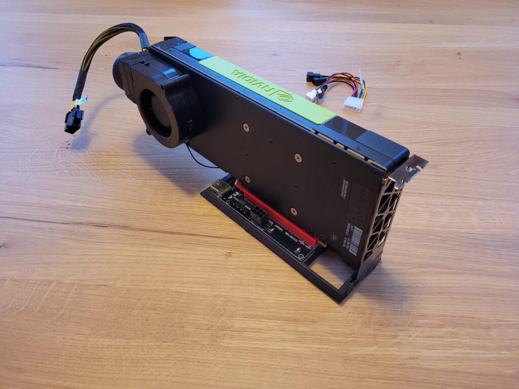
For Private AI in HomeLAB, I was searching for budget-friendly GPUs with a minimum of 24GB RAM. Recently, I came across the refurbished NVIDIA Tesla P40 on eBay, which boasts some intriguing specifications:
GPU Chip: GP102
Cores: 3840
TMUs: 240
ROPs: 96
Memory Size: 24 GB
Memory Type: GDDR5
Bus Width: 384 bit
Since the NVIDIA Tesla P40 comes in a full-profile form factor, we needed to acquire a PCIe riser card.
A PCIe riser card, commonly known as a “riser card,” is a hardware component essential in computer systems for facilitating the connection of expansion cards to the motherboard. Its primary role comes into play when space limitations or specific orientation requirements prevent the direct installation of expansion cards into the PCIe slots on the motherboard.
Furthermore, I needed to ensure adequate cooling, but this posed no issue. I utilized a 3D model created by MiHu_Works for a Tesla P100 blower fan adapter, which you can find at this link: Tesla P100 Blower Fan Adapter.
As for the fan, the Titan TFD-B7530M12C served the purpose effectively. You can find it on Amazon: Titan TFD-B7530M12C.
Currently, I am using a single VM with PCIe pass-through. However, it was necessary to implement specific Advanced VM parameters:
pciPassthru.use64bitMMIO = true
pciPassthru.64bitMMIOSizeGB = 64
Now, you might wonder about the performance. It’s outstanding, delivering speeds up to 16x-26x times faster than the CPU. To provide you with an idea of the performance, I conducted a llama-bench test:
For my project involving the AI tool llama.cpp, I needed to free up a PCI slot for an NVIDIA Tesla P40 GPU. I found an excellent guide and a useful video from ArtOfServer.
Based on this helpful video from ArtOfServer:
ArtOfServer wrote a small tutorial on how to modify an H200A (external) into an H200I (internal) to be used into the dedicated slot (e.g. instead of a Perc6i)
Install compiler and build tools (those can be removed later)
# apt install build-essential unzip
Compile and install lsirec and lsitool
# mkdir lsi
# cd lsi
# wget https://github.com/marcan/lsirec/archive/master.zip
# wget https://github.com/exactassembly/meta-xa-stm/raw/master/recipes-support/lsiutil/files/lsiutil-1.72.tar.gz
# tar -zxvvf lsiutil-1.72.tar.gz
# unzip master.zip
# cd lsirec-master
# make
# chmod +x sbrtool.py
# cp -p lsirec /usr/bin/
# cp -p sbrtool.py /usr/bin/
# cd ../lsiutil
# make -f Makefile_Linux
# lsirec 0000:05:00.0 unbind
Trying unlock in MPT mode...
Device in MPT mode
Kernel driver unbound from device
# lsirec 0000:05:00.0 halt
Device in MPT mode
Resetting adapter in HCB mode...
Trying unlock in MPT mode...
Device in MPT mode
IOC is RESET
Read sbr:
# lsirec 0000:05:00.0 readsbr h200.sbr
Device in MPT mode
Using I2C address 0x54
Using EEPROM type 1
Reading SBR...
SBR saved to h200.sbr
Transform binary sbr to text file:
# sbrtool.py parse h200.sbr h200.cfg
Modify PID in line 9 (e.g using vi or vim):
from this:
SubsysPID = 0x1f1c
to this:
SubsysPID = 0x1f1e
Important: if in the cfg file you find a line with:
SASAddr = 0xfffffffffffff
remove it!
Save and close file.
Build new sbr file:
# sbrtool.py build h200.cfg h200-int.sbr
Write it back to card:
# lsirec 0000:05:00.0 writesbr h200-int.sbr
Device in MPT mode
Using I2C address 0x54
Using EEPROM type 1
Writing SBR...
SBR written from h200-int.sbr
Reset the card an rescan the bus:
# lsirec 0000:05:00.0 reset
Device in MPT mode
Resetting adapter...
IOC is RESET
IOC is READY
# lsirec 0000:05:00.0 info
Trying unlock in MPT mode...
Device in MPT mode
Registers:
DOORBELL: 0x10000000
DIAG: 0x000000b0
DCR_I2C_SELECT: 0x80030a0c
DCR_SBR_SELECT: 0x2100001b
CHIP_I2C_PINS: 0x00000003
IOC is READY
# lsirec 0000:05:00.0 rescan
Device in MPT mode
Removing PCI device...
Rescanning PCI bus...
PCI bus rescan complete.
Exploring the vSphere environment, I’ve found that configuring a large Host Cache with VMFS Datastore can significantly extend reboot times.
It’s a delicate balance of performance gains versus system availability. For an in-depth look at my findings and the impact on your VMware setup, stay tuned.
With vSphere 8.0 update 1, VMware has completed their journey to a completely native end-to-end NVMe storage stack. Prior to 8.0U1, there was a SCSI translation layer which added some complexity to the stack and slightly decreased some of the efficiencies inherent in the NVMe protocol.