Tesla P40 Passthrough GPU Disappears from the VM: “PCIe link to the device is down” on ESXi

My NVIDIA Tesla P40 in ESXi passthrough suddenly vanished from the VM: nvidia-smi could not talk to the driver and a VM reboot did not help. What the logs show, why only a host reboot fixes it, and how to make a homelab P40 stable (KB 418517).

Short answer: When a GPU in ESXi PCI passthrough suddenly disappears from the virtual machine, nvidia-smi says it couldn’t communicate with the NVIDIA driver and the host’s vmkernel.log says Skipping device reset … because PCIe link to the device is down, the card itself has locked up. Neither the guest nor ESXi can reset it, so rebooting the VM does nothing: only a reboot of the ESXi host brings it back (Broadcom KB 418517). That is exactly what happened to the NVIDIA Tesla P40 in my homelab. The lasting fix is to remove the reason the card drops off the bus: in a homelab that is usually heat, power or the PCIe riser.

What happened in my lab

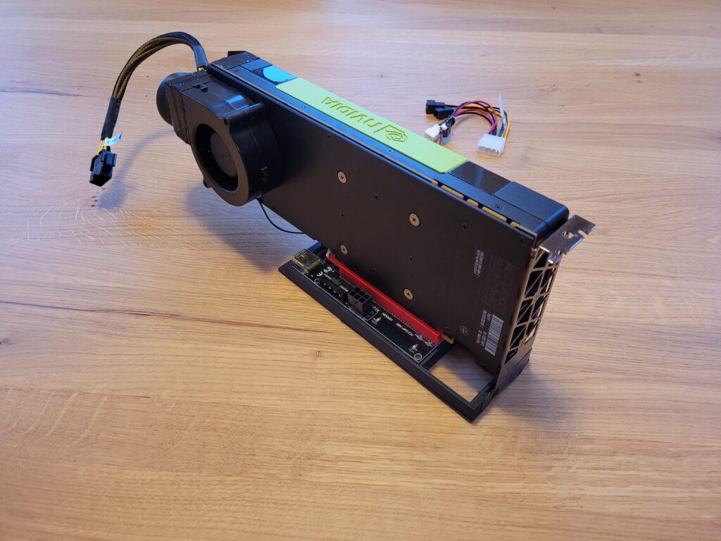
My Tesla P40 runs in PCI passthrough to a single Linux VM for local LLMs. It sits on a PCIe riser and, because the P40 has no fan of its own, it is cooled by a blower fan on a 3D-printed adapter. After running fine for a long time, the GPU was suddenly gone from the VM in the middle of normal work, without any change on vSphere or in the VM:

$ nvidia-smi
NVIDIA-SMI has failed because it couldn't communicate with the NVIDIA driver.
Make sure that the latest NVIDIA driver is installed and running.

Rebooting the VM did not help; the GPU stayed unavailable. The ESXi host told the real story in /var/log/vmkernel.log:

Skipping device reset on <PCIe-ID> because PCIe link to the device is down.

Why a VM reboot does not help

When a VM with a passthrough device powers on or reboots, ESXi resets the PCI device so the guest gets a clean card. That reset needs a working PCIe link. Here the GPU stopped responding at the hardware or firmware level and the link to it went down, so ESXi skips the reset and the guest driver finds nothing it can talk to. The card stays stuck until the host is restarted and the slot is initialized again during boot. Broadcom’s KB describes the same: once a passthrough GPU becomes unresponsive, neither ESXi nor the VM can reset it without a full host reboot.

Confirm it

# in the Linux VM
nvidia-smi
sudo dmesg | grep -iE "nvrm|xid"            # look for Xid errors, e.g. "GPU has fallen off the bus"

# on the ESXi host
grep -iE "PCIe link|device reset" /var/log/vmkernel.log | tail -20
lspci | grep -i nvidia                          # is the card still enumerated?
esxcli hardware pci list | grep -B2 -A12 -i nvidia

Fix: reboot the host

  1. Shut down the VM that uses the GPU (and migrate or shut down the other VMs on that host).
  2. Put the host in maintenance mode and reboot it. If the GPU is still missing after a warm reboot, do a full power cycle so the card loses power completely.
  3. Power the VM on and check nvidia-smi again.

Why it happens, and how to keep a homelab P40 stable

The KB points to GPU hardware or firmware stability and lists what to check with the hardware vendor: card stability, PCIe slot health, GPU firmware or VBIOS, thermal and power conditions, and known reset or firmware lock-up issues. For a data-center card like the P40 running outside its intended server, three of them stand out:

  • Heat. The P40 is passively cooled and expects strong server airflow. A homelab fan adapter that is fine at idle can be too weak under a long inference run. Watch the temperature and throttle reasons during load, and lower the power limit if needed:
    nvidia-smi --query-gpu=temperature.gpu,power.draw,clocks_throttle_reasons.active --format=csv -l 5
    sudo nvidia-smi -pl 200 (default limit 250 W)
  • Power. The P40 draws up to 250 W through an 8-pin CPU (EPS) style connector, not a normal PCIe 8-pin. Use the correct adapter and a power supply rail with enough headroom; a load spike on a weak rail can drop the card.
  • The PCIe path. A riser or extension cable is the first suspect for a link that goes down. Reseat it, try a shorter or better-shielded riser, and if the board allows it, force the slot to PCIe Gen3 (or Gen2 for testing) instead of Auto.

Keep the passthrough settings the large-BAR card needs (pciPassthru.use64bitMMIO = true and pciPassthru.64bitMMIOSizeGB = 64), keep the server BIOS and the NVIDIA guest driver current, and note when the drops happen: always under heavy load points to heat or power, random times at idle point more to the riser or the card itself.

Further reading

Support for nConnect Feature Added in ESXi NFS Client

Use nConnect in ESXi 8.0 U1+ for several TCP connections per NFSv3 datastore: esxcli syntax, limits (4/8/256), runtime changes in 8.0 U2 and how to check.

Short answer: since ESXi 8.0 Update 1 the NFS client supports nConnect: several TCP connections per NFSv3 datastore. Mount with esxcli storage nfs add ... -c <connections> (default 1, up to 4 per datastore, or 8 with /NFS/MaxConnectionsPerDatastore, and 256 per host in total). Since 8.0 Update 2 you can change it on a mounted datastore with esxcli storage nfs param set -v <label> -c <n>. It’s NFSv3 only and CLI only.

With the release of VMware ESXi 8.0 Update 1, VMware quietly introduced nConnect support in the NFS client — a long-awaited enhancement for environments using NFSv3 datastores.

The nConnect feature allows administrators to establish multiple parallel TCP connections per NFS datastore, significantly improving throughput, resiliency, and traffic isolation.

This guide walks you through how to configure nConnect, supported versions, and key operational tips.


🆕 What’s New in ESXi 8.0U1

From ESXi 8.0U1 onwards, a new parameter -c (number of connections) is available in esxcli when mounting NFSv3 datastores.

esxcli storage nfs add \
  -H <host> \
  -v <volume-label> \
  -s <remote_share> \
  -c <number_of_connections>

Key points:

  • Supported for NFSv3 only (NFSv4.1 not yet supported).
  • Currently available only via CLI, not via vCenter UI.
  • Host Profiles don’t officially support it yet (though there’s a workaround, see below).
  • Default max connections per datastore: 4
  • Adjustable up to 8 connections via advanced option:
esxcfg-advcfg -s 8 /NFS/MaxConnectionsPerDatastore

⚠️ The total number of connections across all mounted NFSv3 datastores is capped at 256.


Runtime Scaling in ESXi 8.0U2

The nConnect feature got a useful upgrade in VMware ESXi 8.0 Update 2.
You can now increase or decrease the number of TCP connections on an existing NFSv3 mount without unmounting the datastore:

esxcli storage nfs param set \
  -v <volume-label> \
  -c <number_of_connections>

This flexibility helps admins fine-tune NFS performance on the fly — for example, ramping up connections during heavy backup windows or scaling down during low I/O periods.

Note: In both 8.0U1 and 8.0U2, the default number of connections remains 1.


How to Check Active NFS Connections

To view the number of RPC clients currently used by mounted NFSv3 datastores, run:

vsish -e get /vmkModules/nfsclient/info

Sample output:

NFS Connections Info {
mountedVolumes:10
totalConnections 40
}

This command is particularly handy for performance troubleshooting and capacity planning.


🧪 Experimental: Host Profile Integration

Although official Host Profile support for nConnect is not yet released, VMware added an experimental field named “Number of TCP connections” in:

Host Profile → Storage Configuration → NFS

What it does:
When you set a value here, ESXi will use that number of parallel TCP sessions when mounting the NFS datastore during profile remediation.

This is ideal for consistent deployment across multiple hosts in larger clusters.


Best Practices & Tips

  • Start with 4 connections and scale up as needed after performance testing.
  • Keep the 256 connection limit in mind when mounting multiple datastores.
  • Use consistent configuration across hosts to avoid mount mismatches.
  • Monitor performance metrics via VMware vSphere or CLI.
  • If you’re using Host Profiles, experiment carefully with the TCP connection parameter.

Summary

The nConnect feature in ESXi’s NFS client marks a major step forward in improving NFSv3 performance and scalability in enterprise environments.

Whether you’re running backup workloads, large VMs, or latency-sensitive applications, multiple TCP connections per NFS datastore can make a measurable difference.

If you’re upgrading to VMware ESXi 8.0U1 or later, nConnect is worth testing and adopting in your storage strategy.


Links

vmss2core: Where to Download It and How to Convert VM Snapshots (.vmsn/.vmss + .vmem) into Windows and Linux Memory Dumps

vmss2core in 2026: where to download it, which .vmsn/.vmss/.vmem files it needs, -W/-W8/-N commands, WinDbg analysis and common errors.

Short answer: vmss2core converts a VM checkpoint (a snapshot with memory, .vmsn + .vmem, or a suspend file, .vmss + .vmem) into a memory dump for WinDbg or the Linux crash utility. Get the current build from VMware Workstation Pro or Fusion; the standalone Fling in Broadcom’s Free Downloads is older (build 8456865) and does not support Windows 11, Server 2019 or Server 2025. Run vmss2core.exe -W8 vm.vmsn vm.vmem for modern Windows, -N for Linux.

vmss2core converting a VMware VM snapshot (.vmsn and .vmem) into a memory dump

What the vmss2core tool does and which files it needs

vmss2core reads VMware checkpoint state and writes a core or memory dump that standard debuggers understand: memory.dmp for Windows (WinDbg) or vmss.core for Linux (crash, GDB). It is useful when a guest hangs and you cannot force a crash dump from inside the OS.

MethodFiles to copyNotes
Snapshot with memory<name>-SnapshotN.vmsn + <name>-SnapshotN.vmemVM keeps running. Pick the newest pair by timestamp.
Suspend<name>.vmss + <name>.vmemHardware version 11 or newer, or VMs on vVols, write a separate .vmem. Hardware version 10 or lower keeps everything in the .vmss.

The .vmem file is the guest memory image. The .vmsn/.vmss file holds the device and CPU state. You always pass the state file first and the .vmem second.

vmss2core download: where to get it now

The old Flings site and vmwa.re/flings links are gone. Flings now live in the Free Downloads section of the Broadcom Support Portal, which needs a free Broadcom account (personal email addresses are accepted).

SourceVersionUse it for
Broadcom Support Portal > Free Downloads > Flings > VMSS2CoreLegacy standalone build 8456865 (Windows and Linux binaries)Older guests only. Not for Windows 11, Server 2019 or Server 2025.
VMware Workstation Pro (Free Downloads)Current, bundledAny supported guest, including Windows 11 and Server 2025
VMware Fusion Pro (Free Downloads)Current, bundledSame, on macOS

Once Workstation or Fusion is installed, the binary is here:

  • Windows 64-bit: C:\Program Files (x86)\VMware\VMware Workstation\vmss2core.exe
  • Windows 32-bit: C:\Program Files\VMware\VMware Workstation\
  • Linux: /usr/bin/ (Broadcom’s KB calls the Linux binary vmss2core-Linux64; same syntax)
  • macOS (Fusion): /Library/Application Support/VMware Fusion/

Get the latest vmss2core.exe without installing Workstation

  1. Download the VMware Workstation Pro installer from Free Downloads (Broadcom’s example: VMware-Workstation-Full-25H2u1-25219725.exe).
  2. Open the installer with 7-Zip, then open Workstation.cab inside it.
  3. Copy vmss2core.exe and _zlib1.dll to one folder, for example C:\Temp\vmss2core.
  4. Rename _zlib1.dll to zlib1.dll. Without this you get “The code execution cannot proceed because zlib1.dll was not found.”

Get the snapshot or suspend files from ESXi

vSphere Client datastore browser showing the .vmsn and .vmem snapshot files to download for vmss2core
  1. Reproduce the problem so the guest is in the state you want to capture. The guest kernel must be loaded; a VM stuck in BIOS/POST or before the OS boots gives no usable data.
  2. In the vSphere Client, right-click the VM and take a snapshot with the VM’s memory included, or suspend it (Power > Suspend). From the ESXi Shell you can suspend with vim-cmd vmsvc/getallvms and vim-cmd vmsvc/power.suspend <VMID>.
  3. Browse the datastore to the VM folder (/vmfs/volumes/<datastore>/<vm_name>/) and download the .vmsn or .vmss file and the matching .vmem.
  4. Copy them to the folder that contains vmss2core.

On vSAN the .vmem is an object; Broadcom KB 326327 describes reading its object ID and exposing it with objtool before copying. For Horizon desktops, put full clones in maintenance mode before suspending; for instant clones, use a memory snapshot instead. The Broadcom KBs are written for ESXi 8.x; memory snapshots and suspend work the same way in vSphere 9.

vmss2core for Windows: -W or -W8

OptionGuest OS (Broadcom KB 323788)
-WWindows 7, Windows 10, Windows Server 2008, 2008 R2
-W8Windows 8, 8.1, Windows 11, Windows Server 2012, 2016, 2019, 2025
-NLinux
vmss2core.exe -W8 test-vm.vmsn test-vm.vmem
vmss2core.exe -W8 test-vm.vmss test-vm.vmem
vmss2core.exe -W  old-vm.vmsn old-vm.vmem

KB 181598 phrases it slightly differently: -W8 for Windows 8 / Server 2012 and later, -W for older Windows. The two KBs disagree on Windows 10. Success produces memory.dmp in the current folder.

vmss2core for Linux guests: -N

./vmss2core-Linux64 -N vm-Snapshot1.vmsn vm-Snapshot1.vmem
vmss2core.exe -N vm-Snapshot1.vmsn vm-Snapshot1.vmem

The result is vmss.core, a Red Hat crash-format core. The tool’s help says -N uses kernel structure offsets passed with -l, generated by getlinuxoffsets. Here is my own -N run from the original version of this post (vmss2core build 20800274, about 2,000 MB written, progress lines shortened):

vmss2core.exe -N VM-Snapshot1.vmsn VM-Snapshot1.vmem
vmss2core version 20800274 Copyright (C) 1998-2022 VMware, Inc. All rights reserved.
Started core writing.
Writing note section header.
Writing 1 memory section headers.
Writing notes.
... 100 MBs written.
... 200 MBs written.
...
... 1900 MBs written.
... 2000 MBs written.
Finished writing core.

Analyze the VMware memory dump

  • Windows, WinDbg: windbg -y <SymbolPath> -z memory.dmp, or File > Open Crash Dump (Ctrl+D). Start with !analyze -v, then .bugcheck, lm and !process 0 0.
  • Linux, crash: crash vmlinux vmss.core. crash needs two arguments for a dump file: the uncompressed kernel (vmlinux with debug info matching the guest kernel) and the dump.

vmss2core errors and fixes

SymptomCause and fix
Unrecognized .vmss file (magic 4f434e45), 0 KB memory.dmpVM files are encrypted (Windows 11 / Server 2025 with vTPM). Suspend the VM, decrypt on ESXi with crypto-util (below), convert the decrypted files with the current vmss2core.
Error parsing Windows data. Cannot create memory.dmpWindows kernel was not loaded yet (stuck in POST, no boot device, boot failure). Capture again after the OS is up.
0 KB dump, or a .core file instead of memory.dmpVBS or Hyper-V is enabled in the guest. Check vhv.enable = "TRUE" in the .vmx; the KB says to set it to "FALSE". Also update old Windows builds.
Access is DeniedUse the latest vmss2core from Workstation Pro.
EFI VM freezes on a black screen, Cannot translate linear addressEFI SMM deadlock on hardware version below 14 (ESXi 7.0). Fixed in ESXi 8.0; workaround is hardware version 14 or later (KB 318382).
crypto-util encobj decrypt --related vm-###.vmx vm-###.vmem vm-###-decrypted.vmem
crypto-util encobj decrypt --related vm-###.vmx vm-###.vmss vm-###-decrypted.vmss
vmss2core.exe -W8 vm-###-decrypted.vmss vm-###-decrypted.vmem

Do not remove the vTPM to get around encryption: Broadcom warns that this makes encrypted data unrecoverable and stops Windows 11 from booting.

vmss2core options reference

Output of vmss2core.exe without arguments on my machine (build 20800274, abridged):

Usage:
GENERAL:  vmss2core [[options] | [-l linuxoffsets options]] \
          <vmss file> [<vmem file>]

Without options one vmss.core<N> per vCPU with linear view of
memory is generated.
-q      Quiet(er) operation.
-M      Create core file with physical memory view (vmss.core).
-l str  Offset stringset expressed as 0xHEXNUM,0xHEXNUM,... .
-N      Red Hat crash core file for arbitrary Linux version
        described by the "-l" option (vmss.core).
-N4     Red Hat crash core file for Linux 2.4 (vmss.core).
-N6     Red Hat crash core file for Linux 2.6 (vmss.core).
-O <x>  Use <x> as the offset of the entrypoint.
-U <i>  Create linear core file for vCPU <i> only.
-P      Print list of processes in Linux VM.
-P<pid> Create core file for Linux process <pid> (core.<pid>).
-S      Create core for 64-bit Solaris (vmcore.0, unix.0).
-S32    Create core for 32-bit Solaris (vmcore.0, unix.0).
-W      Create WinDbg file (memory.dmp) with commonly used
        build numbers ("2195" for Win32, "6000" for Win64).
-W<num> Create WinDbg file (memory.dmp), with <num> as the
        build number (for example: "-W2600").
-WK     Create a Windows kernel memory only dump file (memory.dmp).
-WDDB<num> or -W8DDB<num>
        Create WinDbg file (memory.dmp), with <num> as the
        debugger data block address in hex.
-WSCAN  Scan all of memory for Windows debugger data blocks
        (instead of just low 256 MB).
-W8     Generate a memory dump file from a suspended Windows 8 VM.
-X32    <mach_kernel> Create core for 32-bit Mac OS.
-X64    <mach_kernel> Create core for 64-bit Mac OS.
-F      Create core for an EFI firmware exception.

Sources

Related on vdan.cz

Raspberry Pi 5 PCIe Gen 3: Enable 8 GT/s on the External PCIe Connector and Verify the Link Speed

Raspberry Pi 5 runs its external PCIe x1 link at Gen 2 by default. Enable Gen 3 with dtparam=pciex1_gen=3, verify with lspci LnkSta, know the risks.

Short answer: The external PCIe connector on the Raspberry Pi 5 runs PCIe Gen 2.0 x1 (5 GT/s) by default. To switch it to PCIe Gen 3.0 (8 GT/s), add dtparam=pciex1_gen=3 to /boot/firmware/config.txt, or use raspi-config → Advanced Options → PCIe Speed, then reboot. Raspberry Pi states that the Pi 5 is not certified for Gen 3.0, so the link may be unstable. Check the negotiated speed with sudo lspci -vv (the LnkSta line).

Illustration of a Raspberry Pi 5 board with high-speed PCIe signal traces

Raspberry Pi 5 PCIe lanes: what runs at which speed

The BCM2712 SoC on the Raspberry Pi 5 drives two PCIe links. One goes to RP1, Raspberry Pi’s own I/O controller. RP1 handles USB, Gigabit Ethernet, the MIPI camera/display transceivers and GPIO. The other goes to the new 16-pin, 0.5 mm pitch FPC connector on the left edge of the board, which is meant for fast peripherals such as NVMe drives on an M.2 HAT+.

LinkLanesDefaultGen 3.0 option
BCM2712 → RP1 (USB, Ethernet, MIPI, GPIO)x4, PCIe 2.0 (16 Gb/s)Gen 2.0Not affected by pciex1_gen
External FPC connector (M.2 HAT+, NVMe, other PCIe devices)x1Gen 2.0, 5 GT/s (~500 MB/s peak)dtparam=pciex1_gen=3, 8 GT/s, not certified

Only the external x1 link changes. Gen 3.0 roughly doubles its raw signalling rate, from 5 GT/s to 8 GT/s. That is why NVMe benchmarks on the Pi 5 improve noticeably when the drive and the adapter can handle it.

How to enable PCIe Gen 3 on the Raspberry Pi 5

Current Raspberry Pi OS keeps config.txt in the boot partition at /boot/firmware/config.txt. The original version of this post used /boot/config.txt, which was the path on older images. Edit whichever file your image actually boots from.

Option 1: config.txt

  1. If the device is not a HAT+ board, turn on the connector first. HAT+ devices are detected automatically, so they don’t need this line. nvme is an alias for pciex1.
  2. Add the Gen 3 line and reboot with sudo reboot.
# /boot/firmware/config.txt
dtparam=pciex1
dtparam=pciex1_gen=3

The Raspberry Pi kernel overlay README describes both parameters. pciex1 “enable[s] the external PCIe link” (default off), and pciex1_gen sets the GEN/speed of that link (default 2).

Option 2: raspi-config

  1. Run sudo raspi-config.
  2. Select Advanced Options → PCIe Speed.
  3. Choose Yes to enable PCIe Gen 3 mode, then Finish.
  4. Reboot with sudo reboot.

Check the PCIe link speed with lspci

After the reboot, look at the link capability and status of the PCIe devices. You need lspci from the pciutils package.

sudo lspci -vv | grep -E "^[0-9a-f]|LnkCap:|LnkSta:"
  • LnkCap shows what the device or port supports.
  • LnkSta shows what was actually negotiated. For the external connector and the device behind it, Speed 8GT/s with Width x1 means Gen 3.0 is active. 5GT/s means the link is still at Gen 2.0.
  • The output also lists the RP1 link. That one stays at Gen 2.0, which is expected.

Is PCIe Gen 3 on the Raspberry Pi 5 safe?

Raspberry Pi’s documentation says the Raspberry Pi 5 isn’t certified for Gen 3.0 speeds and that Gen 3.0 connections might be unstable. Whether it works depends on the ribbon cable, the adapter board and the device. If the drive doesn’t enumerate, disappears, or logs PCIe/NVMe errors in dmesg, go back to the default: remove the pciex1_gen=3 line (or set it to 2) and reboot. Don’t enable Gen 3 on a system you can’t afford to debug, especially if you boot from the NVMe drive.

Booting the Raspberry Pi 5 from NVMe

In most homelab builds, the reason to care about PCIe speed is an NVMe boot drive. Boot from PCIe is not enabled by default. Edit the bootloader configuration with sudo rpi-eeprom-config --edit and set:

BOOT_ORDER=0xf416
# only for a non-HAT+ adapter:
PCIE_PROBE=1

Save and reboot to write the EEPROM. The official M.2 HAT+ (2230/2242) and M.2 HAT+ Compact (2230) are specified as single-lane PCIe 2.0 adapters with up to 3 A for the M.2 device. Anything above Gen 2.0 on them falls under the same “not certified” caveat.

Sources

Further reading (benchmarks): Jeff Geerling: Forcing PCI Express Gen 3.0 speeds on the Pi 5 and Testing PCIe on the Raspberry Pi 5.

Related on vdan.cz

NVIDIA Tesla P40 for Private AI in the Homelab: Specs, ESXi Passthrough and Benchmarks

Tesla P40 specs (24 GB GDDR5, 250 W, 10.5-inch dual slot, compute 6.1), cooling and ESXi passthrough setup, llama.cpp benchmarks, and CUDA 13 limits.

Short answer: the NVIDIA Tesla P40 is a 2016 Pascal data-center GPU with 24 GB GDDR5, a 250 W power limit and a dual-slot, 10.5-inch PCIe Gen3 card with no fan of its own. It’s one of the cheapest ways to get 24 GB of VRAM for local LLMs in a homelab. It runs fine with ESXi PCIe passthrough and in my tests was 16–26× faster than the CPU in llama.cpp. The catch in 2026: CUDA 13 no longer targets Pascal, so you stay on CUDA 12.x.

Tesla P40 specifications

Architecture / GPUPascal, GP102
CUDA cores3,840
Compute capability6.1
Memory24 GB GDDR5, 384-bit
Max power250 W
Form factorDual-slot, 10.5-inch, full height, PCI Express Gen3 x16
CoolingNo fan: designed for server airflow
INT8 inference47 TOPS

Source: NVIDIA Tesla P40 datasheet; compute capability as reported by CUDA in the benchmark output below.

Why I picked the P40

For Private AI in HomeLAB, I was searching for budget-friendly GPUs with a minimum of 24GB RAM. Recently, I came across the refurbished NVIDIA Tesla P40 on eBay, which boasts some intriguing specifications:

  • GPU Chip: GP102
  • Cores: 3840
  • TMUs: 240
  • ROPs: 96
  • Memory Size: 24 GB
  • Memory Type: GDDR5
  • Bus Width: 384 bit

Fitting and cooling the P40 in a homelab

Since the NVIDIA Tesla P40 comes in a full-profile form factor, we needed to acquire a PCIe riser card.

A PCIe riser card, commonly known as a “riser card,” is a hardware component essential in computer systems for facilitating the connection of expansion cards to the motherboard. Its primary role comes into play when space limitations or specific orientation requirements prevent the direct installation of expansion cards into the PCIe slots on the motherboard.

Furthermore, I needed to ensure adequate cooling, but this posed no issue. I utilized a 3D model created by MiHu_Works for a Tesla P100 blower fan adapter, which you can find at this link: Tesla P100 Blower Fan Adapter.

As for the fan, the Titan TFD-B7530M12C served the purpose effectively. You can find it on Amazon: Titan TFD-B7530M12C.

ESXi PCIe passthrough settings

Currently, I am using a single VM with PCIe pass-through. However, it was necessary to implement specific Advanced VM parameters:

  • pciPassthru.use64bitMMIO = true
  • pciPassthru.64bitMMIOSizeGB = 64

If the P40 later disappears from the VM and nvidia-smi can no longer reach the driver, see Tesla P40 passthrough GPU disappears: “PCIe link to the device is down”. A VM reboot doesn’t help there; only a host reboot brings the card back.

llama.cpp benchmark: P40 vs CPU

Now, you might wonder about the performance. It’s outstanding, delivering speeds up to 16x-26x times faster than the CPU. To provide you with an idea of the performance, I conducted a llama-bench test:

pp 512CPU t/sGPU t/sAcceleration
llama 7B mostly Q4_09.50155.3716x
llama 13B mostly Q4_05.18134.7426x
./llama-bench -t 8
| model                          |       size |     params | 
| ------------------------------ | ---------: | ---------: | 
| llama 7B mostly Q4_0           |   3.56 GiB |     6.74 B | 
| llama 7B mostly Q4_0           |   3.56 GiB |     6.74 B | 
| backend    |    threads | test       |              t/s |
| ---------- | ---------: | ---------- | ---------------: |
| CPU        |          8 | pp 512     |      9.50 ± 0.07 |
| CPU        |          8 | tg 128     |      8.74 ± 0.12 |
./llama-bench -ngl 3800
ggml_init_cublas: GGML_CUDA_FORCE_MMQ:   no
ggml_init_cublas: CUDA_USE_TENSOR_CORES: yes
ggml_init_cublas: found 1 CUDA devices:
  Device 0: Tesla P40, compute capability 6.1
| model                          |       size |     params |
| ------------------------------ | ---------: | ---------: |
| llama 7B mostly Q4_0           |   3.56 GiB |     6.74 B |
| llama 7B mostly Q4_0           |   3.56 GiB |     6.74 B |
| backend    | ngl | test       |              t/s | 
| ---------- | --: | ---------- | ---------------: | 
| CUDA       | 3800 | pp 512     |    155.37 ± 1.26 |
| CUDA       | 3800 | tg 128     |      9.31 ± 0.19 |
 ./llama-bench -t 8 -m ./models/13B/ggml-model-q4_0.gguf
| model                          |       size |     params |
| ------------------------------ | ---------: | ---------: |
| llama 13B mostly Q4_0          |   6.86 GiB |    13.02 B |
| llama 13B mostly Q4_0          |   6.86 GiB |    13.02 B |
| backend    |    threads | test       |              t/s |
| ---------- | ---------: | ---------- | ---------------: |
| CPU        |          8 | pp 512     |      5.18 ± 0.00 |
| CPU        |          8 | tg 128     |      4.63 ± 0.14 |
./llama-bench -ngl 3800 -m ./models/13B/ggml-model-q4_0.gguf
ggml_init_cublas: GGML_CUDA_FORCE_MMQ:   no
ggml_init_cublas: CUDA_USE_TENSOR_CORES: yes
ggml_init_cublas: found 1 CUDA devices:
  Device 0: Tesla P40, compute capability 6.1
| model                          |       size |     params |
| ------------------------------ | ---------: | ---------: |
| llama 13B mostly Q4_0          |   6.86 GiB |    13.02 B |
| llama 13B mostly Q4_0          |   6.86 GiB |    13.02 B |
| backend    | ngl | test       |              t/s | 
| ---------- | --: | ---------- | ---------------: | 
| CUDA       | 3800 | pp 512     |    134.74 ± 1.29 |
| CUDA       | 3800 | tg 128     |      8.42 ± 0.10 |

Feel free to explore this setup for your Private AI in HomeLAB.

Is the Tesla P40 still worth it in 2026?

  • CUDA: CUDA Toolkit 13.0 removed offline compilation and library support for Maxwell, Pascal and Volta. You can keep building for the P40 with CUDA 12.x, but newer toolkits can’t target it (CUDA 13.1 release notes).
  • Still good for: running quantized models that need a lot of VRAM on a budget, where 24 GB matters more than raw speed.
  • Plan for: power (250 W) and your own airflow, because the card has no fan.

Related: vGPU management in VMware environments.

DELL R610 or R710: How to Convert an H200A to H200I for Dedicated Slot Use

Convert a Dell H200A to an H200I so it fits the R610/R710 dedicated storage slot and frees a PCIe slot, e.g. for an NVIDIA Tesla P40.

For my project involving the AI tool llama.cpp, I needed to free up a PCI slot for an NVIDIA Tesla P40 GPU. I found an excellent guide and a useful video from ArtOfServer.

Based on this helpful video from ArtOfServer:

ArtOfServer wrote a small tutorial on how to modify an H200A (external) into an H200I (internal) to be used into the dedicated slot (e.g. instead of a Perc6i)

ArtOfServer wrote a small tutorial on how to modify an H200A (external) into an H200I (internal) to be used into the dedicated slot (e.g. instead of a Perc6i)

Install compiler and build tools (those can be removed later)

# apt install build-essential unzip

Compile and install lsirec and lsitool

# mkdir lsi
# cd lsi
# wget https://github.com/marcan/lsirec/archive/master.zip
# wget https://github.com/exactassembly/meta-xa-stm/raw/master/recipes-support/lsiutil/files/lsiutil-1.72.tar.gz
# tar -zxvvf lsiutil-1.72.tar.gz
# unzip master.zip
# cd lsirec-master
# make
# chmod +x sbrtool.py
# cp -p lsirec /usr/bin/
# cp -p sbrtool.py /usr/bin/
# cd ../lsiutil
# make -f Makefile_Linux

Modify SBR to match an internal H200I

Get bus address:

# lspci -Dmmnn | grep LSI
0000:05:00.0 "Serial Attached SCSI controller [0107]" "LSI Logic / Symbios Logic [1000]" "SAS2008 PCI-Express Fusion-MPT SAS-2 [Falcon] [0072]" -r03 "Dell [1028]" "6Gbps SAS HBA Adapter [1f1c]"

Bus address 0000:05:00.0

We are going to change id 0x1f1c to 0x1f1e

Unbind and halt card:

# lsirec 0000:05:00.0 unbind
Trying unlock in MPT mode...
Device in MPT mode
Kernel driver unbound from device
# lsirec 0000:05:00.0 halt
Device in MPT mode
Resetting adapter in HCB mode...
Trying unlock in MPT mode...
Device in MPT mode
IOC is RESET

Read sbr:

# lsirec 0000:05:00.0 readsbr h200.sbr
Device in MPT mode
Using I2C address 0x54
Using EEPROM type 1
Reading SBR...
SBR saved to h200.sbr

Transform binary sbr to text file:

# sbrtool.py parse h200.sbr h200.cfg

Modify PID in line 9 (e.g using vi or vim):
from this:
SubsysPID = 0x1f1c
to this:
SubsysPID = 0x1f1e

Important: if in the cfg file you find a line with:
SASAddr = 0xfffffffffffff
remove it!
Save and close file.

Build new sbr file:

# sbrtool.py build h200.cfg h200-int.sbr

Write it back to card:

# lsirec 0000:05:00.0 writesbr h200-int.sbr
Device in MPT mode
Using I2C address 0x54
Using EEPROM type 1
Writing SBR...
SBR written from h200-int.sbr

Reset the card an rescan the bus:

# lsirec 0000:05:00.0 reset
Device in MPT mode
Resetting adapter...
IOC is RESET
IOC is READY
# lsirec 0000:05:00.0 info
Trying unlock in MPT mode...
Device in MPT mode
Registers:
DOORBELL: 0x10000000
DIAG: 0x000000b0
DCR_I2C_SELECT: 0x80030a0c
DCR_SBR_SELECT: 0x2100001b
CHIP_I2C_PINS: 0x00000003
IOC is READY
# lsirec 0000:05:00.0 rescan
Device in MPT mode
Removing PCI device...
Rescanning PCI bus...
PCI bus rescan complete.

Verify new id (H200I):

# lspci -Dmmnn | grep LSI
0000:05:00.0 "Serial Attached SCSI controller [0107]" "LSI Logic / Symbios Logic [1000]" "SAS2008 PCI-Express Fusion-MPT SAS-2 [Falcon] [0072]" -r03 "Dell [1028]" "PERC H200 Integrated [1f1e]"

You can now move the card to the dedicated slot 🙂

Thanks to ArtOfServer for a great video.

VMware ESXI and Intel Optane NVMe – intelmas firmware update

How to install intelmas tool

[~] esxcli software component apply -d /vmfs/volumes/SSD/_ISO/intel-mas-tool_2.2.18-1OEM.700.0.0.15843807_20956742.zip
Installation Result
   Components Installed: intel-mas-tool_2.2.18-1OEM.700.0.0.15843807
   Components Removed:
   Components Skipped:
   Message: Operation finished successfully.
   Reboot Required: false

Common information about the disc

[~] /opt/intel/intelmas/intelmas show -intelssd 1

- 1 Intel(R) Optane(TM) SSD 905P Series PHMB839000LW280IGN -

Bootloader : EB3B0416
Capacity : 260.83 GB (280,065,171,456 bytes)
DevicePath : nvmeMgmt-nvmhba5
DeviceStatus : Healthy
Firmware : E201HPS2
FirmwareUpdateAvailable : The selected drive contains current firmware as of this tool release.
Index : 1
MaximumLBA : 547002287
ModelNumber : INTEL SSDPED1D280GAH
NamespaceId : 1
PercentOverProvisioned : 0.00
ProductFamily : Intel(R) Optane(TM) SSD 905P Series
SMARTEnabled : True
SectorDataSize : 512
SerialNumber : PHMB839000LW280IGN

S.M.A.R.T information

[~] /opt/intel/intelmas/intelmas show -nvmelog SmartHealthInfo -intelssd 1

-  PHMB839000LW280IGN -

- NVMeLog SMART and Health Information -

Volatile memory backup device has failed : False
Temperature has exceeded a critical threshold : False
Temperature - Celsius : 30
Media is in a read-only mode : False
Power On Hours : 0x0100
Power Cycles : 0x03
Number of Error Info Log Entries : 0x0
Controller Busy Time : 0x0
Available Spare Space has fallen below the threshold : False
Percentage Used : 0
Critical Warnings : 0
Data Units Read : 0x02
Available Spare Threshold Percentage : 0
Data Units Written : 0x0
Unsafe Shutdowns : 0x0
Host Write Commands : 0x0
Device reliability has degraded : False
Available Spare Normalized percentage of the remaining spare capacity available : 100
Media Errors : 0x0
Host Read Commands : 0x017F

Show all the SMART properties for the Intel® SSD at index 1

[~] /opt/intel/intelmas/intelmas show  -intelssd 1 -smart

- SMART Attributes PHMB839000LW280IGN -

- B8 -

Action : Pass
Description : End-to-End Error Detection Count
ID : B8
Normalized : 100
Raw : 0

- C7 -

Action : Pass
Description : CRC Error Count
ID : C7
Normalized : 100
Raw : 0

- E2 -

Action : Pass
Description : Timed Workload - Media Wear
ID : E2
Normalized : 100
Raw : 0

- E3 -

Action : Pass
Description : Timed Workload - Host Read/Write Ratio
ID : E3
Normalized : 100
Raw : 0

- E4 -

Action : Pass
Description : Timed Workload Timer
ID : E4
Normalized : 100
Raw : 0

- EA -

Action : Pass
Description : Thermal Throttle Status
ID : EA
Normalized : 100
Raw : 0
ThrottleStatus : 0 %
ThrottlingEventCount : 0

- F0 -

Action : Pass
Description : Retry Buffer Overflow Count
ID : F0
Normalized : 100
Raw : 0

- F3 -

Action : Pass
Description : PLI Lock Loss Count
ID : F3
Normalized : 100
Raw : 0

- F5 -

Action : Pass
Description : Host Bytes Written
ID : F5
Normalized : 100
Raw : 0
Raw (Bytes) : 0

- F6 -

Action : Pass
Description : System Area Life Remaining
ID : F6
Normalized : 100
Raw : 0

Disk firmware update

[~] /opt/intel/intelmas/intelmas load -intelssd 1
WARNING! You have selected to update the drives firmware!
Proceed with the update? (Y|N): Y
Checking for firmware update...

- Intel(R) Optane(TM) SSD 905P Series PHMB839000LW280IGN -

Status : The selected drive contains current firmware as of this tool release.

How to Maxtang’s NX 6412 NUC add to vDS? Fix script /etc/rc.local.d/local.sh

The Maxtang NX6412 loses its vDS uplink after an ESXi reboot with USB NICs. The /etc/rc.local.d/local.sh script that fixes it.

How to fix network after adding to vDS. When you add NX6412 to vDS and reboot ESXi. I don’t have uplink for vDS. You could check it with:

# esxcfg-vswitch -l
DVS Name         Num Ports   Used Ports  Configured Ports  MTU     Uplinks
vDS              2560        6           512               9000    vusb0
--cut
  DVPort ID                               In Use      Client
  468                                     0           
  469                                     0
  470                                     0
  471                                     0

We will have to note DVPort ID 468 – example. vDS is name of your vDS switch.

esxcfg-vswitch -P vusb0 -V 468 vDS

It is necessary add it to /etc/rc.local.d/local.sh before exit 0. You could have similar script from source Persisting USB NIC Bindings

vusb0_status=$(esxcli network nic get -n vusb0 | grep 'Link Status' | awk '{print $NF}')
count=0
while [[ $count -lt 20 && "${vusb0_status}" != "Up" ]]
do
    sleep 10
    count=$(( $count + 1 ))
    vusb0_status=$(esxcli network nic get -n vusb0 | grep 'Link Status' | awk '{print $NF}')
done

esxcfg-vswitch -R
esxcfg-vswitch -P vusb0 -V 468 vDS

exit 0

What’s the story with Optane?

Intel is winding down Optane. What it means if you use Optane SSDs in a homelab (e.g. TrueNAS ZIL/L2ARC) or Optane with ESXi.

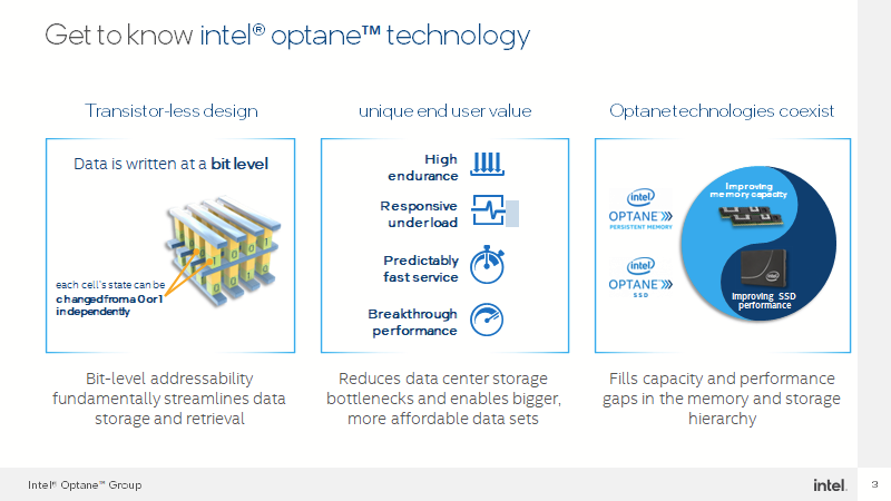
I am using Intel SSD Optane 900P PCIe in my HomeLAB as ZIL L2ARC drives for TrueNAS, but in July of 2022 Intel announced their intention to wind down the Optane business. I will try summary information about Intel Optane from Simon Todd presentation.

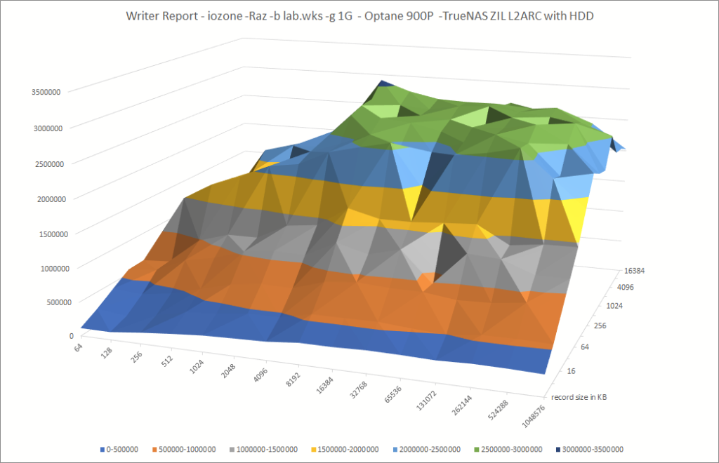
My HomeLAB benchmark Optane 900P -TrueNAS ZIL L2ARC with HDD

Optane help a lot with IOPs for RAID with normal HDD. I reach 2,5GB/s peak write performance.

Writer Report – iozone -Raz -b lab.wks -g 1G – Optane 900P -TrueNAS ZIL L2ARC with HDD x-axis File size in KB; z-axis MB/s
Writer Report – iozone -Raz -b lab.wks -g 1G – Optane 900P -TrueNAS ZIL L2ARC with HDD

We call see great write performance for 40GB file size set about 1,7GB/s.

# perftests-nas ; cat iozone.txt
        Run began: Sun Dec 18 08:02:39 2022

        Record Size 128 kB
        File size set to 41943040 kB
        Command line used: /usr/local/bin/iozone -r 128 -s 41943040k -i 0 -i 1
        Output is in kBytes/sec
        Time Resolution = 0.000001 seconds.
        Processor cache size set to 1024 kBytes.
        Processor cache line size set to 32 bytes.
        File stride size set to 17 * record size.

              kB  reclen    write  rewrite    read    reread
        41943040     128  1734542  1364683  2413381  2371527

iozone test complete.
# dd if=/dev/zero of=foo bs=1G count=1
1+0 records in
1+0 records out
1073741824 bytes transferred in 1.517452 secs (707595169 bytes/sec) 707 MB/s

# dd if=/dev/zero of=foo bs=512 count=1000
1000+0 records in
1000+0 records out
512000 bytes transferred in 0.012079 secs (42386853 bytes/sec) 42 MB/s

Intel® Optane™ Business Update: What Does This Mean for Warranty and Support

As announced in Intel’s Q2 2022 earnings, after careful consideration, Intel plans to cease future development of our Optane products. We will continue development of Crow Pass on Sapphire Rapids as we engage with key customers to determine their plans to deploy this product. While we believe Optane is a superb technology, it has become impractical to deliver products at the necessary scale as a single-source supplier of Optane technology.

We are committed to supporting Optane customers and ecosystem partners through the transition of our existing memory and storage product lines through end-of-life. We continue to sell existing Optane products, and support and the 5-year warranty terms from date of sale remain unchanged.

Get to know intel® optane™ technology
Source Simon Todd – vExpert – Intel Webinar Slides

What makes Optane SSD’s different?

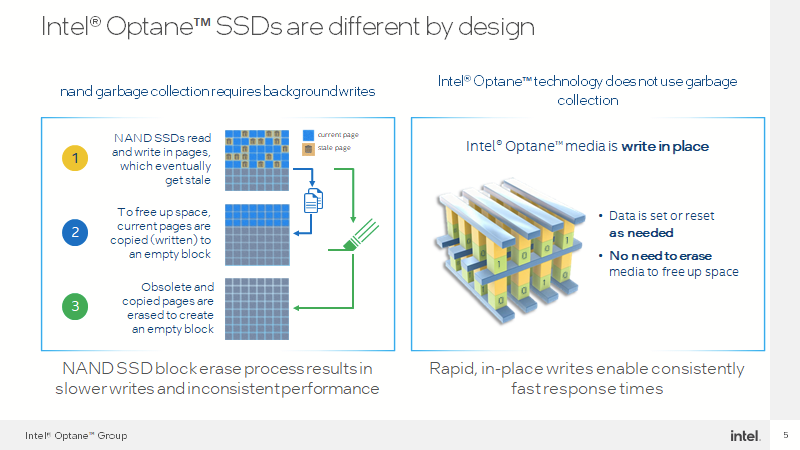
    NAND SSD

    NAND garbage collection requires background writes. NAND SSD block erase process results in slower writes and inconsistent performance.

    Intel® Optane™ technology

    Intel® Optane™ technology does not use garbage collection
    Rapid, in-place writes enable consistently fast response times

    Intel® Optane™ SSDs are different by design
    Source Simon Todd – vExpert – Intel Webinar Slides
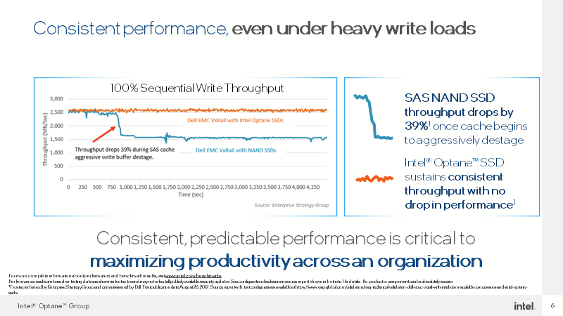
    Consistent performance, even under heavy write loads
    Source Simon Todd – vExpert – Intel Webinar Slides
    ModelDies per channelChannelsRaw CapacitySpare Area
    Intel Optane SSD 900p 280GB37336 GB56 GB
    Intel Optane SSD DC P4800X 375GB47448 GB73 GB
    Intel Optane SSD 900p 480GB57560 GB80 GB
    Intel Optane SSD DC P4800X 750GB87896 GB146 GB
    The Optane SSD DC P4800X and the Optane SSD 900p both use the same 7-channel controller, which leads to some unusual drive capacities. The 900p comes with either 3 or 5 memory dies per channel while the P4800X has 4 or 8. All models reserve about 1/6th of the raw capacity for internal use Source

    Intel Optane SSD DC P4800X / 900P Hands-On Review

    Wow, How is Optane fast …

    The Intel Optane SSD DC P4800X is slightly faster than the Optane SSD 900p throughout this test, but either is far faster than the flash-based SSDs. Source

    Maxtang’s NX 6412 NUC – update ESXi 8.0a

    Update a Maxtang NX6412 NUC to ESXi 8.0a (CVE-2022-31705 fix): build a custom ESXi 8.0a ISO with the USB Network Native Driver.

    VMware ESXi 8.0a release was announced:

    How to prepare ESXi Custom ISO image 8U0a for NX6412 NUC?

    Download these files:

    Run those script to prepare Custom ISO image you should use PowerCLI version 13.0. Problem with upgrade to PowerCLI you could fix with blog PowerCLI 13 update and installation hurdles on Windows:

    Add-EsxSoftwareDepot .\VMware-ESXi-8.0a-20842819-depot.zip
    Add-EsxSoftwareDepot .\ESXi800-VMKUSB-NIC-FLING-61054763-component-20826251.zip
    New-EsxImageProfile -CloneProfile "ESXi-8.0a-20842819-standard" -name "ESXi-8.0.0-20842819-USBNIC" -Vendor "vdan.cz"
    Add-EsxSoftwarePackage -ImageProfile "ESXi-8.0.0-20842819-USBNIC" -SoftwarePackage "vmkusb-nic-fling"
    Export-ESXImageProfile -ImageProfile "ESXi-8.0.0-20842819-USBNIC" -ExportToBundle -filepath ESXi-8.0.0-20842819-USBNIC.zip

    Upgrade to ESXi 8.0

    TPM_VERSION WARNING: Support for TPM version 1.2 is discontinued. With Apply –no-hardware-warning option to ignore the warnings and proceed with the transaction.

    esxcli software profile update -d  /vmfs/volumes/datastore1/_ISO/ESXi-8.0.1-20842819-USBNIC.zip -p ESXi-8.0.1-20842819-USBNIC --no-hardware-warning
    Update Result
       Message: The update completed successfully, but the system needs to be rebooted for the changes to be effective.
       Reboot Required: true